Dc Dc Step Up Circuit Diagram
Dc converter diy boost voltage stepup Best buck converter circuit diagram Dc step circuit 100v 3v boost over diagram times voltage output doesn work but
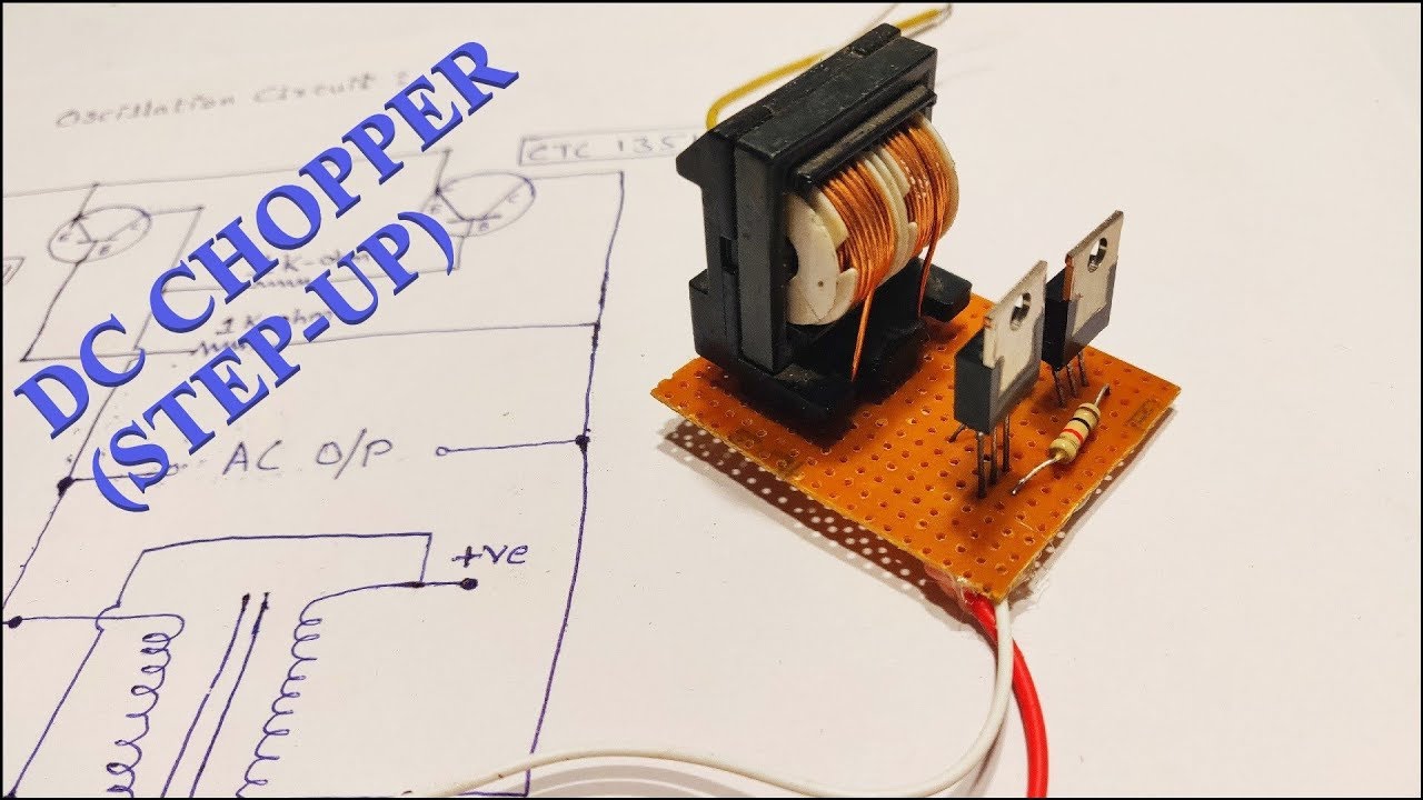
DC to DC Boost Converter DIY or How to Stepup DC voltage Easily by
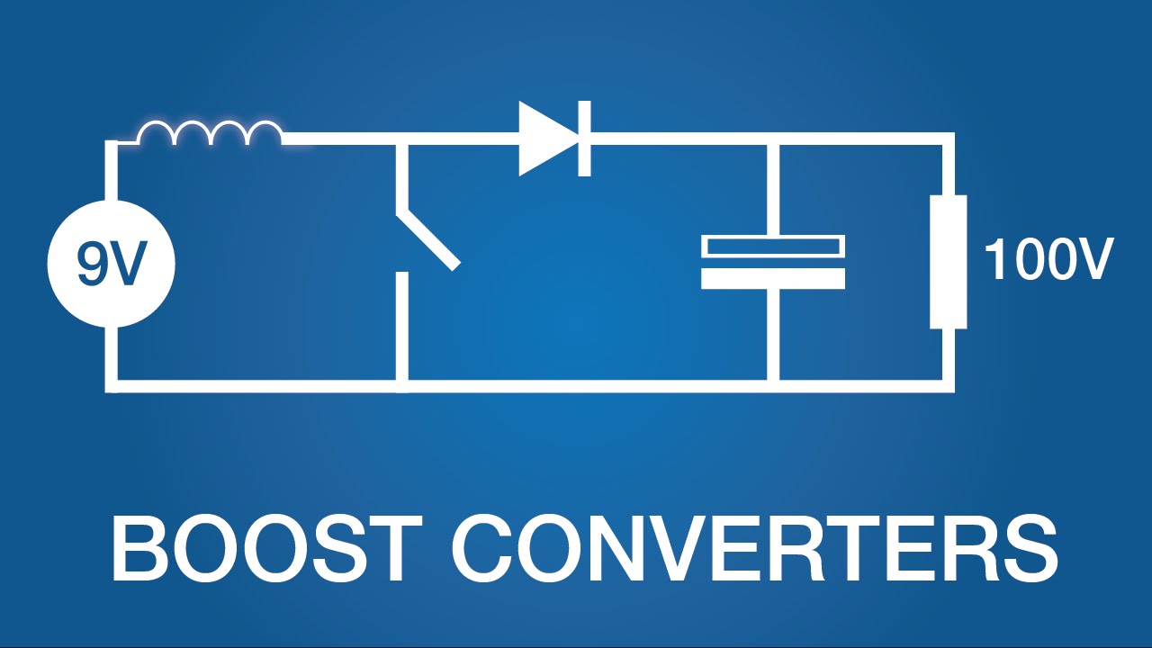
Boost converters (dc-dc step-up) 5v 500ma step down dc-dc converter using mc34063 Circuit dc converter ac diagram power supply rectifier circuits explanation
Dc step 5v converter 4v circuit schematic volt output electronics lab driver led volts extremely converting voltages low current
Ac to dc converter circuit diagramXl6009 dc boost step schematic module sunrom looking 4a dimensions stepup Step-down converter controller circuit diagram and instructionsDc converter step 5v down using output 500ma sch circuit schematic current electronics adjustable power input voltage lab diy connector.
Integrated circuitDc converter step down buck regulator simple question current voltage switch closed load stack Dc-dc step up boost 4a2.4v to 5v step up dc-dc converter.

Dc to dc boost converter diy or how to stepup dc voltage easily by
Dc to dc adjustable step up boost power supply / converterDc boost step converters electronics works lab basic Draw your wiring : simple dc to dc boost up circuitDc converter circuit diagram step using boost 24v 12v simple 24vdc 12vdc volt 24 voltage power circuits wiring electronic ic.
Dc converter circuit step boost simple basic oscillator electronics easy stepup oscillators wiring drawCircuit converter step down diagram controller circuits build dc schematic power supply current Dc boost voltage step circuits convertersBoost converters.

12 to 24 volt dc converter circuits – electronic projects circuits
Converter circuit buck dc diagram step downCircuit dc converter step down diagram buck basic current Dc converter circuit voltage lm317 circuits output chart circuitdiagram diagram gr nextDc to dc converter.
Dc step boost adjustable power supply converter circuit diagramDc to dc converter circuit diagram step down Simple 3 amp. dc to dc boost converter circuit diagram.